
![]() So I have had many conversation over the years in regards of that is MTU and how does it work and what is the relationship between frame/packet/datagram sizes. Despite the fact that this is actually fairly simple there seems to be a lot of confusion on this topic so that is why this article come about.
So I have had many conversation over the years in regards of that is MTU and how does it work and what is the relationship between frame/packet/datagram sizes. Despite the fact that this is actually fairly simple there seems to be a lot of confusion on this topic so that is why this article come about.
Ethernet
So the basics are quite simple minimal legal Ethernet frame length is 64B without the VLAN shim and 68B with it. There is a corner case with frame being 64B and having a VLAN tag (which is a valid frame until it reaches the de-capsulation point) but that is not really relevant here. In reality most equipment only adds encapsulation on top of the existing frame so this never really happens outside test environment.
The maximal defined legal length of Ethernet frame is 1518B with all headers and shims. It is implied that all the additional headers should be taken from the payload data space – yes from those 1500B but that leads to very high overhead resulting in sometimes quite bad data transport inefficiency. Most devices will actually allow frames that are larger than 1518B. As the size limitations became very obvious most vendors introduced and adopted jumbo-frames. These are non-standard size Ethernet frames usually defined as over 9000B. The size of jumbo frame accepted by device differs from vendor to vendor and appliance to appliance. Frames that are between the Jumbo frames and the 1518B legal size are usually called MiniGiants.
Setting Ethernet (L2) MTU on juniper router
ge-0/0/0 {
    mtu 1518;
    unit 0 {
        family inet {
            address 10.0.0.0/31;
        }
    }
}
The above will only set Ethernet MTU and it is a safe value to use in most cases.
IP
The minimal size of IP packet 46B and maximal is 1500B including the IP headers. The smallest possible header for IPv4 is 20B the larges total length of an IP packet is 65535. This is more or less theoretical as even jumbo frames are usually only 9000B on IP layer. There are some instances where this number can be even larger. The most important thing to note here is that the Ethernet MTU and IP MTU are two different and separate numbers though they are interdependent.
Setting IP (L3) MTU on juniper router
ge-0/0/0 {
    unit 0 {
        family inet {
            mtu 1500;
            address 10.0.0.0/31;
        }
    }
}
The above will only set IP MTU. This is a safe default to use in most cases.
Issues with segmentation
There is a lot of issues with incorrectly set MTU and/or mismatched L2/L3 MTUs. In IPv4 this is solved usually solved by fragmentation on the router that has smaller MTU on egress interface. But the fragmentation process is very demanding on the router and will result in heightened CPU and buffer utilization – sometimes to the point for dropping the fragmented packet and subsequent re-transmission by higher layer protocols. This issues are exacerbated in scenarios with IPsec tunneling as the checksums calculated on the payload would be invalidated by fragmentation. Thus the DF bit is set to 1 – do-not fragment. Similar issues could be encountered while using non-native Ethernet WANs with additional encapsulation headers.
Path MTU Discovery
To check the minimal common MTU for the whole path the PMTU tool can be used. It uses the don’t fragment flag (DF) in the IP header and on top it is usually ICMP. The mechanism is simple as the sender transmits largest packet possible to each next hop in traceroute-like fashion and when the packet is too large the hop will send back ICMP message “fragmentation needed”. Then the sender decreases the MTU size until it will get through the ultimate hop.
This method of MTU discovery is a bit crude and has some disadvantages but is quite useful for fist view of the problem and it is a good way to start if investigating this type of issues.
TCP
TCP header is between 20B and 60B in size with maximal segment size of 65415B. In TCP terms segment is the payload without any headers (IP or TCP itself). The segment size is declared to the receiving end of the 3-way handshake but it can be altered by L4 capable devices in the path of the syn packet. This is a bit complicated to explain so let’s see how the 3-way handshake looks like in real life.
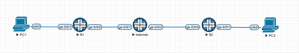
In our example PC-1 is initiating the TCP session towards PC-2. There is an IPsec tunnel between R1 and R2 on which we can set the TCP clamping and see the result on the traffic between the end-hosts.
The capture below is the 3-way handshake as seen on eth0 of PC-1.
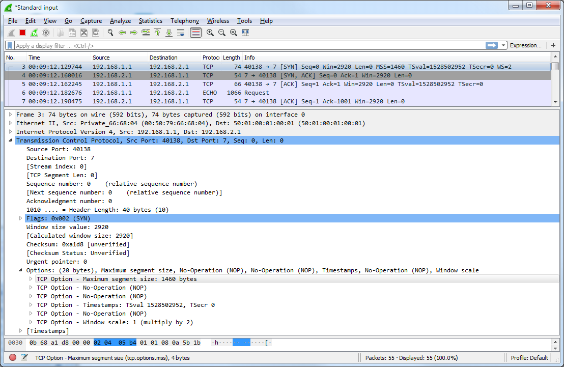
You can notice two things here – the initial window size is set to 2920B which will fit exactly two TCP segments of the proposed size of 1460B. Why it is 2 segments and not just one or three ? Well 2 is a default segment multiplier as implemented in Linux TCP/IP stack so the smallest window will always contain at least 2 segments.
In the tunnel interface setup I have configured the TCP MSS clamping in order to alter the values in the syn packet to 1000B before it will the IPsec tunnel between R1 and R2. This will signal the max Segment size to the remote end of the TCP session.
This is how to configure the clamp:
root@R1# show security flow
tcp-mss {
    ipsec-vpn {
        mss 1000;
    }
}
The result on the eth0 on PC-2 reflect this as you can see in the received pcap.
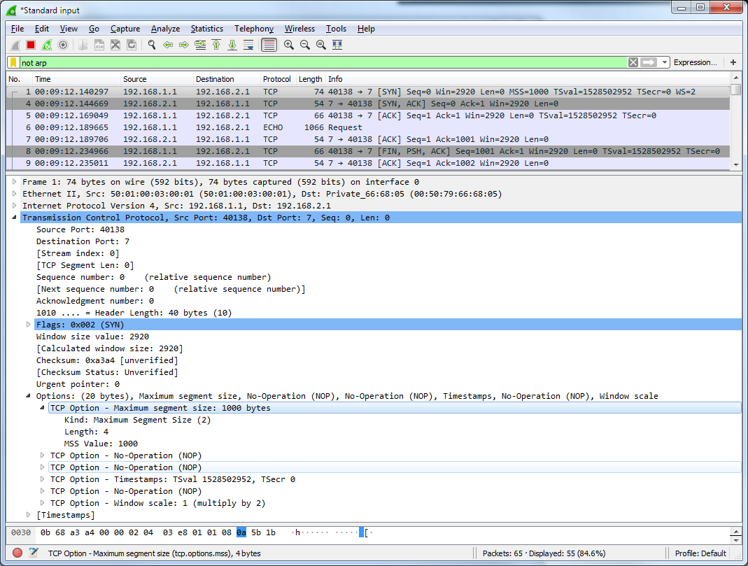
The receiving end gets the information about the decreased segment size. But in the SYN ACK response message it will send the default segment size (in my case 1460B (which is my interface’s IP MTU of 1500 with 40B TCP overhead deducted). On PC-1 we would see that this option/value is neighter changed by the above mentioned configuration and nor by the TCP handshake process. This seem weird but in this case it is a configuration issue as the IPsec tunnel should have the MSS clamping applied symmetrically on both ends of the tunnel.
root@R2# show security flow
tcp-mss {
    ipsec-vpn {
        mss 1000;
    }
}
The issue is if you need to do TCP clamping but you don’t necessarily have control of both ends of the tunnel yet you need to clamp both the SYN and the returning SYN ACK so the path would have symmetric setup for the MTU/MSS. The reason for this is that you not only want to avoid fragmentation (or drops in IPsec case) but also because this could lead to following traffic pattern in the TCP windowing:
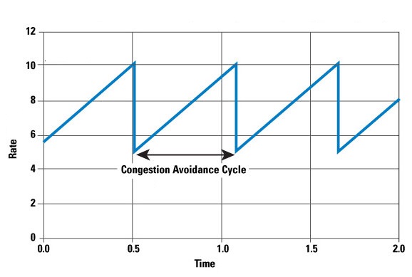
This is known as TCP oscillation or TCP saw-tooth and every of this graph peak is a point where the TCP window is reset resulting in re-transmissions with extremely poor performance and instability of the connections across the link. Fortunately this issue can be resolved in multiple ways – in configuration of your device it could be achieved by global TCP mss configuration.
root@R1# show security flow
tcp-mss {
    all-tcp {
        mss 1000;
    }
}
This setting will intercept any TCP SYN or SYN ACK datagrams and will adjust the MSS size accordingly. This might be a bit of a too harsh of a solution as it impacts all TCP traffic passed through the device but it can be useful.
There is also a possibility that the upper layer protocols will take care of things for you or that some external tool, like the aforementioned PMTU discovery, will instruct them regardless of the path’s configuration.
Configuring and Testing the MTU and MSS clamping on a IPsec/VPN tunnel
First it is important to make very clear statement that should be obvious by now from the previous parts of the article but the IP and Ethernet MTU are not the same – they must differ by at least 14 Bytes but usually I would set them 18B apart to accommodate a single vlan (802.1Q) shim. If you actually set the same values for the L2 and L3 MTU junos will actually warn you that it is an invalid configuration:
[edit interfaces ge-0/0/0 unit 0 family]
'inet'
Family MTU 1500 is too large relative to device MTU 1500; Protocol overhead should be 14
So the correct interface config should look something like this :
ge-0/0/0 {
    mtu 1518
    unit 0 {
        family inet {
            mtu 1500;
            address 10.0.0.0/31;
        }
    }
}
It is always good practice to set both values. The issue is how to decide to what to set the MSS and where.
The RFC 879 suggest the following (conservative) formula:
MSS = MTU - 60 - 60 = MTU - 120
So in our case that would be 1500 – 120=1380. This is quite ineffective and assumes that the IP header will be full 60B long – which is not our case as only 20B header is used in this test so we could use the more optimistic formula:
MSS = MTU - 20 - 20 = MTU - 40
This would result in MSS of 1460B which sounds much more reasonable. So now we need to apply it to the IPsec traffic in both directions and we’re done.
root@R1# show security flow
tcp-mss {
    ipsec-vpn {
        mss 1460;
    }
}
Final note on testing
There are couple things to remember if you will be testing this from the juniper devices.
- The MSS setting will not affect ICMP (duh!) so if you want to test the MTU size the st0 unit must be set with relevant IP MTU.
- Junos adds headers on top of the size you defined as the size is really length of the payload.
So in effect the following command:
ping 10.0.0.1 size 1400
will result in frame that is 1442B long. The breakdown of the packet makeup is shown below.
| 14B ethernet | 20B IP | 8B ICMP | 1400 payload |
If there is a PC ideally a linux box that can be used for the end-to-end path MTU discovery the tracepath application is what you could use. There is great article on packetlife that has some nice pictures and examples.